Intermatic Dt101 Wiring Diagram
No ground wire is hooked up or in the box anywhere. 24-Hour Mechanical Time Switch 120 VAC 60Hz SPST Indoor Metal Enclosure 1 Hour Interval.

Reviews For Intermatic Dt Series 1 Circuit 20 Amp 24 Hour Indoor Surface Mount Timer With Battery Backup Gray Dt101d89 The Home Depot
These dependable time switches can handle electrical loads up to 40 A per pole and allow for up to 12 ONOFF operations per day.

Intermatic dt101 wiring diagram. Intermatic t101 timer wiring diagram how to connect 24 hour time clock switch page 1 t103 pool t101p201 instruction manual mechanical wire an t104r won t turn pump on 120 volts hb 1492 apt troubleshooting with grasslin for one bf 1613 electrical outlet timers dt101 line photocell supplementary model 277 volt triumph schematic my box. Here is the important part. 120v supply to line load neut.
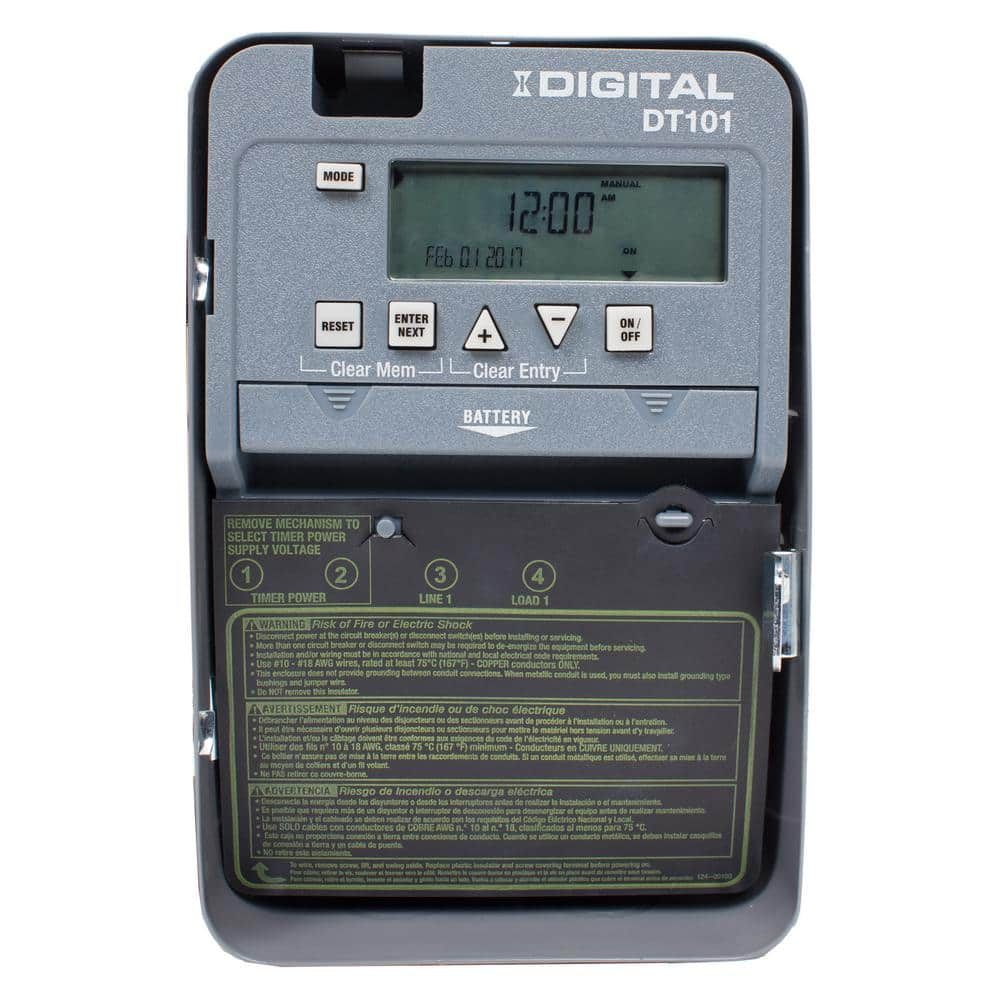
Cmon Intermatic you must be able to do better. This is a review of their DT101 24-hr Digital time switch. Is it as simple as transferring the wires to the dt101.
The T100 Series Mechanical Time Switch has proven it can stand the test of time. The switch is rated for a 1 HP motor at 120V. Unless you are an electrician if you simply use the Intermatic supplied wiring diagram you will misunderstand and likely wire it incorrectly and thing its bad out of the box.
The Intermatic T101R mechanical timer is an easy-to-use device for automatically controlling lights pool pumps or any other load that you want to switch on and off at set times each day. What concerns me is the T101 is rated for 40 amps and the new dt101 is only rated for 20 amps. Item 1 Intermatic DT101 Series 1-Circuit 20 Amp 24 Hour Indoor Timer w Battery Backup 1 - Intermatic DT101 Series 1-Circuit 20 Amp 24 Hour Indoor Timer w Battery Backup.
A neutral a gray line 1 purple and load 2 black. BRAND NEW IN BOX - INTERMATIC 24-HR DIGITAL TIME SWITCH DT101. Wiring diagram pressure plate terminal screw make sure wire insulation clears pressure plate minimum copper wire size awg max.
We show where to connect the neutral wire. Youtube the unit for wiring. Intermatic is dedicated to providing energy management solutions for commercial residential and industrial markets.
Use the DT101 as an ONOFF timer in applications requiring 24-hour load control such as lighting air conditioning systems pumps etc. Theres nothing to complain about the full-featured guts to this device. DT101 is housed in a lockable enclosure to prevent vandalism and unauthorized tampering.
Shipped with USPS Priority Mail. All circuits usually are the same. The Intermatic DT101 Digital 24-Hour Time Switch automatically switches loads to a preset daily schedule with to-the-minute accuracy.
Youtube for explain wiring. Intermatic dt101 wiring diagram. I am replacing an intermatic T101 with a new DT101 and there are only three wires hooked up to the T101.
How To Wire A Pe153 Digital Timer To A 2 Speed 230v Motor How To Wire And Connect A Intermatic Pool Pump Timer T101r Youtube How To Wire T101 Timer. Intermatic et70115c time switches. Intermatic Timer Wiring Diagram T101 Source.
To control two 120v devices the. Where the black hot wire goes. Upon rst use you must set the Date and Time before you can program any other settings.
The T101R can be set to switch a load on and off up to 12 times a day using color-coded pegs inserted into the timer wheel. This may be fine for a 120v circuit however it is not safe to do on a 240v circuit unless the timer does not carry voltage to that 3 terminal when it is on. A manual override switch provides added.
A picture of the back of the pump and the wiring instructions are attached. Something The wiring information for the T10R Intermatic Pool Timer and the Instructions are attached. Intermatic incorporated 158ts10941 spring grove illinois 60081-9698 time pointer time dial off tripper manual lever on tripper clock motor ground a 1 2 grd.
The power to the Intermatic is a three pronged 15 A 125V plug that is connected to its own GFI circuit or whatever you call it It was installed for the pool pump. It works the wiring diagram could be better but once wiring is done its very easy to set up. Voltage ground individual component and buttons.
Depending on how the timer is switched internally if you look at the wiring diagram the jumper wire between terminals 2 and 3 are carrying the 120v to terminal 3 regardless if the timer is on or off. The batteries are easy to replace and do not require removing the time switch mechanism or field wiring. Intermatic Dt101 Wiring Diagram Ditulis thesun Minggu 04 Februari 2018 Tulis Komentar Edit.
Intermatic t101 wiring diagram view 15 best intermatic t101 timer wiring diagram images. The carcass was designed for three loads but its wired for only one.
Intermatic Wiring Diagram Flilpfloppinthrough
Intermatic Wiring Diagram Flilpfloppinthrough

Dt101 Timer Wiring Intermatic T101 Supplementary Manual

Intermatic Wiring Diagram Flilpfloppinthrough
How To Wire Intermatic T104 And T103 And T101 Timers
Intermatic Timer Wiring Diagram Flilpfloppinthrough
Intermatic Dt101 Wiring Diagram Hidupkudibumiini

How To Wire Connect Intermatic Pool Pump Timer Simple Short Video Youtube
Intermatic Wiring Diagram Flilpfloppinthrough
Intermatic Timer Wiring Diagram Flilpfloppinthrough

Intermatic Dt101 Wiring Diagram Hidupkudibumiini

Intermatic Et1100 Series 24 Hour Time Switch Timing Relay Youtube

How To Wire And Connect A Intermatic Pool Pump Timer T101r Youtube
Intermatic Wiring Diagram Flilpfloppinthrough
Intermatic Timer Wiring Diagram Flilpfloppinthrough
How To Wire Intermatic T104 And T103 And T101 Timers


