Gast Air Compressor Wiring Diagram
All air compressors shown have open motors. Step 7 Make sure all wires are neatly tucked back in the compartment.

Diagram Of Auto Ac System In 2021 Air Compressor Pressure Switch Car Air Conditioning Wiring Diagram
A wiring diagram is a streamlined standard photographic representation of an electric circuit.
Gast air compressor wiring diagram. Check filtermuffler 11 for compacted debris. Compressed Air and Vacuum Systems. With a compact yet durable and rugged construction the DAA provides oil-less operation which ensures that the discharge air remains free of lubricant contamination.
Check that power. Gast Air Motor Manual. How to wire air conditioner compressor.
At times the cables will cross. Rotary Vane Compressors and Vacuum Pumps. Re-inspect for wear conditions.
Use only Gast AH255B Flushing Solvent or other non-petroleum based flushing solvent. Gallons in System to Pump to 40 PSI in 30 min. Oilless Piston Air Compressors Max.
The wiring diagram attached to the product provides required electrical information. Accessories The products intake and exhaust filters will provide adequate filtration in most applications. All tank units are wired for 115 volts.
In support of NFPA Standard 13 Model Number Free Air Flow at 40 PSI CFM. The wiring diagram supplied with the product provides required electrical information. This video gives a simple concise description of the components on a typical portable contractor-style gas-powered air compressor.
Tighten both of the screws hand tight. Dual voltage motors are shipped pre-wired for the higher voltage. How To Wire a Gast AT05 Rotary Vane Compressor.
The air line should be the same size or. Variety of ac compressor wiring diagram. Its well suited for noise sensitive environments like medical laboratory applications due to the low noise and vibration operation.
Injunction of two wires is generally indicated by black dot to the intersection of 2 lines. Septic Solutions - Gast Rotary Vane Air Pump Installation Tutorial. Gast DOA and DOL Diaphragms.
Your safety and the safety of others is extremely important. Air MotorsGear Motors Lubricated and Non-Lubricated. Single phase motors have internal thermal protection.
DOA-P701-AA DOL-701-AA DOA-P501-BN DOA-P501-JH. Step 2 The motor on the compressor is shipped wired for 110 volt use. This video shows you how to wire an HVAC ac compressor.
What line size should be used for Gast air motors. This switch is designed to meet NFPA-13 standards for initial pump up time and is rated for 300 gallons 40 PSI and 725 gallons 18 PSI has the ability to set cut in and cut out pressures with the touch of a button and includes a feature to avoid tampering of installation settings. This simply explains wh.
Check that power source is correct to properly operate the dual-voltage motor. UL Listed Oilless Piston Air Compressors for Dry Sprinkler Systems. There will be main lines that are represented by L1 L2 L3 and so on.
I go over the location where each wire needs to go where the. Gast recommends a filter regulator and lubricator be placed within twenty inches of the air motor. We have provided many important safety messages in this manual and on your product.
Consult your Gast representative for additional filter recommendations. Always read and obey all safety messages. It reveals the elements of the circuit as simplified shapes as well as the power and signal connections in between the tools.
The wiring diagram attached to the product provides required electrical information. To change the wiring to 220 volt single phase use two wires need to be moved. Silent oil-free compressor systems Compact elegant designs are ideal for laboratory beverage dental and other applications that require clean quiet oil-free compressed air.
Now replace the cover plate under the two hex head screws. As stated previous the lines in a Air Compressor Wiring Diagram signifies wires. Check that power source is correct to properly operate the dual-voltage motors.
1AM 1UP 2AM 4AM 6AM 8AM 16AM and Gear Motors. But it does not imply link between the cables. Wiring diagram white supplied by motor vendor applied by thomas warning label red supplied by motor vendor applied by thomas motor nameplate provided by motor supplier 1149 relief valve 435 435 350 695 1020 14 npt exhaust wiring diagram white supplied by motor vendor applied by thomas warning label red supplied by.

New 2 Pole 3 Phase Motor Wiring Diagram Baldor Motors Wiring Electric Motor Wiring Electric Motor Wiring Diagram Wiring Diagram

Split Air Conditioning System Warehouse Shop A Midea 21 Seer 4 9000 Btu 4 Zone Cassett Heat Pump Air Conditioner Ductless Air Conditioner Air Conditioner Units

Diagram Wiring Diagram For Ac Blower Motor Full Version Hd Quality Blower Motor Trudiagram Amicideidisabilionlus It
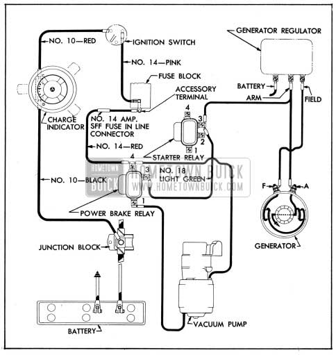
Wiring Diagram For Vacuum Pump

Diagram Gast 86r Compressor Wiring Diagram Full Version Hd Quality Wiring Diagram Veediagram Amicideidisabilionlus It

Unique Wiring Diagram Ac Split Mitsubishi Refrigeration And Air Conditioning Hvac Air Conditioning Hvac Air

Diagram 2003 Chevy C4500 Wiring Diagram Full Version Hd Quality Wiring Diagram Obadiagram Amicideidisabilionlus It

Air Bag Wiring Dat Wiring Diagrams Air Ride Wiring Diagram Ac Compressor

Pin On Airbrush Diy

Wiring Diagram For 220 Volt Single Phase Motor Http Bookingritzcarlton Info Wiring Diagram For 220 V Circuit Diagram Ac Capacitor Electrical Circuit Diagram

Air Compressor Pressure Switch Wiri Wiring Diagram Floraoflangkawi Org Air Compressor Pressure Switch Air Compressor Wiring Diagram

Proper Installation Wiring Procedure Wiring To The Air Compressor S Pressure Switch Youtube

Diagram Door Air Lift Wiring Diagrams Full Version Hd Quality Wiring Diagrams Imdiagram Giardinowow It

Diagram Chevy C4500 Wiring Diagram Full Version Hd Quality Wiring Diagram Codiagram Amicideidisabilionlus It

Diagram Husky 835 522 Air Compressor Wiring Diagram Full Version Hd Quality Wiring Diagram Ldiagrams Giardinowow It
Gast Roa Raa Series Oilless Vacuum Pump Fuse Electrical Electrical Wiring


Gas Fireplace Wiring Diagram Air Ride Diagram Car Alternator

Ingersoll Rand Air Compressor Wiring Diagram Electrical Wiring Diagram Air Compressor Pressure Switch Wiring Diagram

Diagram Spdt Toggle Switch Wiring Diagram Full Version Hd Quality Wiring Diagram Imdiagram Giardinowow It