System Sensor Rts151key Wiring Diagram
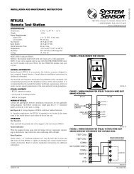
Figure 5 2-Wire Duct Smoke Detector to RTS151RTS151KEY Wiring Diagram Important Notes. See Figure 8 for wiring diagram of RTS151 with Duct Smoke Detectors.

Rts151key System Sensor Keyed Remote Test Reset Station Total Life Safety Solutions
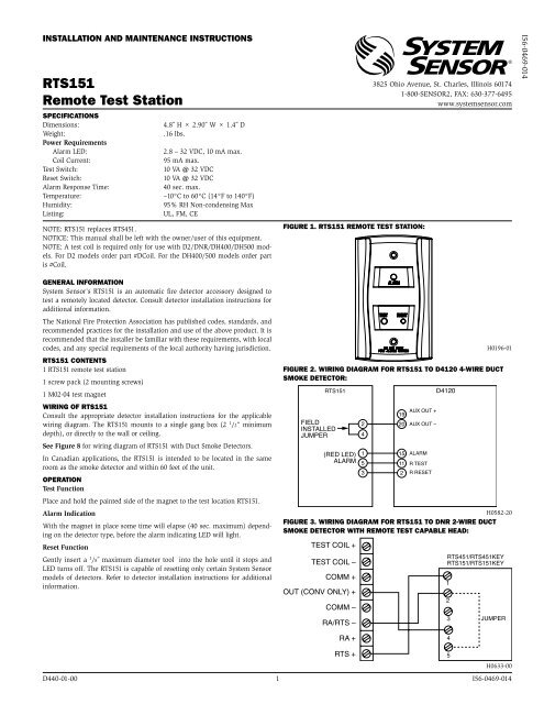
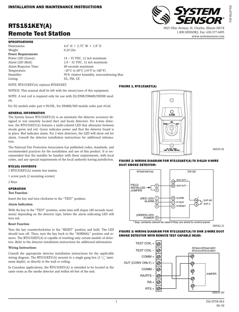
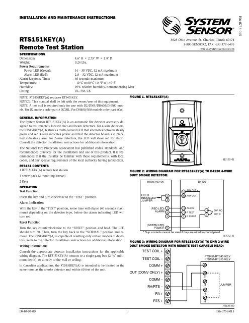
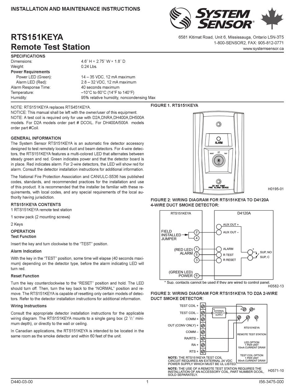
The System Sensor RTS151KEY is an automatic fire detector accessory de-signed to test remotely located duct and beam detectors.

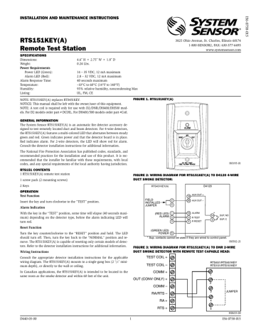
System sensor rts151key wiring diagram. WIrInG of rtS151 Consult the appropriate detector installation instructions for the applicable wiring diagram. Share on Social Media. Terminal 6 of the RTS451KEY is not used when wired to a 2-wire detector.
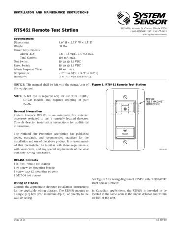
System Sensor Smoke Detector Wiring Diagram Simple Diagrams. Model d4120 and d4s duct smoke detectors utilize 4 wire photoelectric technology for the detection of smoke. Wiring Instructions Consult the appropriate detector installation instructions for the applicable wiring diagram.
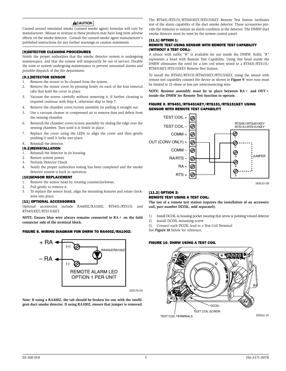
RTS151RTS151KEY JUMPER 4 5 3 2 1 TEST COIL TEST COIL COMM OUT CONV ONLY COMM RARTS RA RTS Wiring for Intelligent Non-Relay Duct Smoke Detector COMM. Green indicates power and that the detector board is in place. Wiring diagram for RTS451KEY to DH100ACDC 4-Wire duct smoke detector.
System wiring diagram for DNR. WIRING OF RTS151 Consult the appropriate detector installation instructions for the applicable wiring diagram. In Canadian applications the RTS151KEY is intended to be located in the same room as the smoke detector and within 60 feet of the unit.
In Canadian applications the RTS151KEY-A is intended to be located in the. Consult the appropriate detector installation instructions for the applicable wiring diagram. 24 VACDC or 120 VAC.
Wiring Instructions Consult the appropriate detector installation instructions for the applicable wiring diagram. See Figure 8 for wiring diagram of RTS151 with Duct Smoke Detectors. H0612-12 24 vac 10 15 full wave rectified unfil tered power ma y be used rts151keya optional remote test station magnet test switch alarm led red 4 5 2 1 ra rts ra test coil test coil in out d2 24 vdc aux power supplied.
Rts151key A Remote Test Station System Sensor. Consult the appropriate detector installation instructions for the applicable wiring diagram. Posted February 26 2021.
The RTS151KEY-A mounts to a single gang box 25 mini-mum depth 635 cm or directly to the wall or ceiling. For 4-wire detectors the RTS151KEY features a multi-colored LED that alternates between steady green and red. OFF RESET TEST H0195-01 H0582-12 fIGURE 1.
In Canadian applications the RTS151KEYA is intended to be located in the same room as the smoke detector and within 60 feet of the unit. H0195-01 H0582-21 fIGURE 1. RTS151KEY Wiring SEE RTS151KEY INSTALLATION INSTRUCTIONS FOR ELECTRICAL RATINGS OF RTS151KEY WIRING Note.
The RTS151KEY System Sensor mounts to a single gang box 2 1 2 minimum depth or directly to the wall or ceiling. Wiring diagram for 2-wire duct smoke detector to RTS151RTS151KEY Remote Test Station Important Note The use of either RTS151 or RTS151KEY requires the installation of an accessory coil DCOIL sold separately. System sensor rts451 wiring diagram.
Wiring diagram for rts151keya to d2 2-wire duct smoke detector. Wiring diagram for RTS451KEY to DH100 2-Wire duct smoke detector. In Canadian applications the RTS151KEYA is intended to be located in the same room as the smoke detector and within 60 feet of the unit.
Consult the appropriate detector installation instructions for the applicable. Built-in short circuit protection from operator wiring errors. The RTS151KEYA mounts to a single gang box 2 12 mini-mum depth or directly to the wall or ceiling.
Two DPDT Form-C relay contacts. The RTS151 mounts to a single gang box 2 12 minimum depth or directly to the wall or ceiling. 44 01444 238820 Fax.
Refer to the detector installation instructions for additional information. 44 01444 248123 Email. System Sensor D4120 Duct Detectors Connected The Right Way.
LINE ULFM LISTED CONTROL PANEL 1ST DETECTOR IN LOOP 2ND DETECTOR IN LOOP COMM. The RTS151KEY mounts to a single gang box 2 12 minimum depth or directly to the wall or ceiling. The RTS151KEY A is capable of resetting only certain models of detec-.
Compatible with existing System Sensor duct smoke products including remote accessories RTS151 and RTS151KEY. Wiring for 2-wire Duct Smoke Detector System wiring diagram for 2-wire duct smoke detectors powered from initiating device circuit. D4120 Duct Smoke Detector System Sensor.
The RTS151 System Sensor mounts to a single gang box 2 12 minimum depth or directly to the wall or ceiling. High contrast terminal designations and wiring diagram label make wiring easy. Wiring of RTS151 System Sensor.
The RTS151RTS151KEY test coli circuit requires an external 24vdc power supply Charles Avenue Burgess Hill RH15 9TQ United Kingdom Tel. All wiring must be installed in accordance with local requirements. The RTS151 mounts to a single gang box 2 12 minimum depth or directly to the wall or ceiling.
Figure 4 2-Wire Duct Smoke Detector Powered from the Initiating Device Circuit Wiring Diagram Figure 5 illustrates the wiring diagram for 2-wire duct smoke detector to the RTS151RTS151KEY Remote Test Station. The use of either the RTS151 or RTS151KEY requires the installation of an. LINE Important Notes he use of.
Before working on the system notify the proper authorities that the system is undergoing maintenance and will be temporarily out of service. The RTS151KEY A mounts to a.
Rts151key A Remote Test Station System Sensor

System Sensor Dh Series Duct Detector To Rts151 Wiring Testing And Explanation Youtube

D4120 Duct Smoke Detector D4s Sensor Component D4p120 Power Board Component Pdf Free Download

Innovairflex Series D2 Duct Smoke Detector Gamewell Fci Manualzz
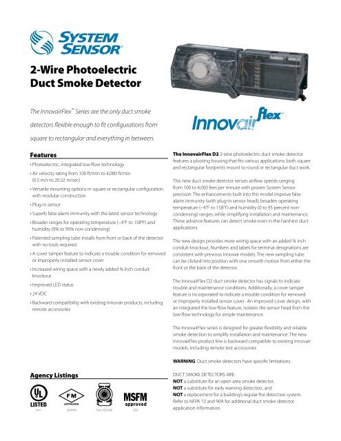
2 Wire Photoelectric Duct Smoke Detector System Sensor

System Sensor Convention 4 Wire Duct Smoke Detector D4120 Wiring Instructions Youtube
System Sensor Rts151key Product Manual Manualzz
Duct Smoke Detector Wiring Diagram Wiring Site Resource

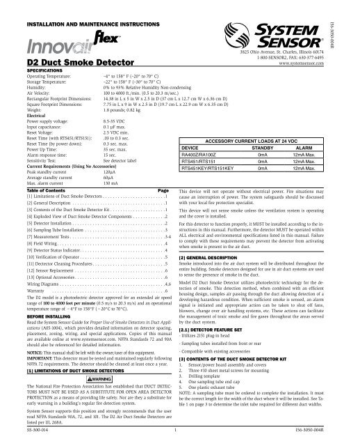
D2 Duct Smoke Detector System Sensor

D4120
Rts151 Remote Test Station System Sensor
System Sensor Rts151key Installation And Maintenance Instructions Pdf Download Manualslib
Wiring A Hvac Ducted Smoke Detector Easy Way Youtube
Https Www Manualshelf Com Manual System Sensor Rts151key Owner Manual English Html
Rts151key A Remote Test Station System Sensor

Rts151 To System Sensor D4120 Duct Detector Wiring And Testing Procedure Youtube
System Sensor Rts451 User Manual Manualzz
Ra Ra System Sensor Dnrw User Manual Page 5 6
System Sensor Rts151keya Installation Instructions Pdf Download Manualslib